Leave Your Message
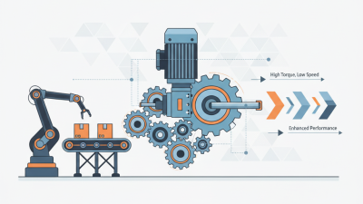
A Motor Reducer combines an electric motor with a gearbox to deliver controlled mechanical power. It reduces output speed while increasing usable torque. This simple change helps machines move heavier loads with better control.
Inside the housing, gears transfer rotation through carefully selected ratios. A motor turning at 1,750 revolutions per minute may drive an output shaft at 175 revolutions per minute. The ten-to-one ratio produces slower movement and higher torque, although efficiency losses remain. Common designs include helical, worm, bevel, and planetary gearboxes. Each design suits different demands, such as conveyors, lifting equipment, packaging lines, or robotic joints.
A reliable explanation must look beyond the ratio. Heat, lubrication, vibration, alignment, and duty cycle strongly affect service life. In practical maintenance work, a reducer that sounds louder than usual may already need inspection. Leaking oil, rising temperature, or uneven motion should not be ignored. Selecting the correct unit requires checking torque, speed, load direction, starting conditions, and operating environment. No reducer is perfect. Worm gears can offer strong reduction, but they may generate more heat. Planetary systems are compact and efficient, but usually cost more. These trade-offs matter.
This guide explains how a Motor Reducer works, how power travels through its gears, and how engineers evaluate performance. It also considers common mistakes in selection and maintenance. Some explanations simplify real machines. That is worth remembering. Actual performance depends on design quality, installation accuracy, and operating conditions.
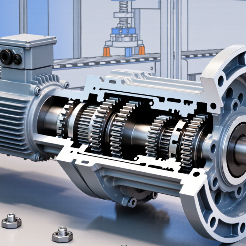
A motor reducer is a mechanical transmission that lowers motor speed and increases usable torque. It usually combines gears, shafts, bearings, seals, and a lubricated housing. The ratio describes the relationship between input and output speed. With a 3:1 reducer, a 1,800 rpm motor produces roughly 600 rpm at the output. A 300:1 unit may deliver about 6 rpm from the same motor. These figures are ideal estimates; load, efficiency, and slip affect real performance.
How does it work? Gears with different tooth counts exchange speed for turning force. The smaller gear spins faster, while the larger gear turns more slowly and carries greater torque. A multi-stage design reaches high ratios without using one enormous gear. However, torque gain is not perfectly proportional to the ratio. A 100:1 reducer with 85 percent efficiency provides approximately 85 times the motor torque. Heat and friction consume part of the input power. This is where datasheet reading matters.
In workshop applications, I check rated torque, peak loads, duty cycle, mounting position, and shaft alignment. A conveyor may need steady torque, while a positioning axis may need low backlash. Poor alignment can create noise, vibration, and premature bearing wear. I have seen a correctly sized reducer overheat because its housing lacked airflow. That mistake is easy to miss. Selecting the highest ratio is not always wise; it can reduce output speed too far and increase starting stress. A practical choice balances speed, torque, efficiency, backlash, and service conditions.
| Motor Reducer Concept | Definition or Calculation | Typical Engineering Data | Practical Effect |
|---|---|---|---|
| Motor reducer | A mechanical transmission that lowers motor speed and increases output torque. | Common reduction ratios range from approximately 3:1 to 300:1, depending on the design and number of stages. | The driven shaft turns more slowly but can deliver substantially greater torque than the motor shaft. |
| Reduction ratio | Reduction ratio = input speed ÷ output speed. | A 10:1 reducer produces one output revolution for every ten input revolutions. | Higher ratios provide greater speed reduction but may increase size, heat generation, backlash, or cost. |
| Speed reduction at 3:1 | Output speed = 1,800 rpm ÷ 3. | 600 rpm output speed; ideal torque multiplication is approximately 3 times. | Suitable for moderate speed reduction where compact size and relatively high efficiency are important. |
| Speed reduction at 5:1 | Output speed = 1,800 rpm ÷ 5. | 360 rpm output speed; ideal torque multiplication is approximately 5 times. | Often used for conveyors, rotary equipment, and general machine drives. |
| Speed reduction at 10:1 | Output speed = 1,800 rpm ÷ 10. | 180 rpm output speed; ideal torque multiplication is approximately 10 times. | A common ratio for material handling, mixers, feeders, and automated machinery. |
| Speed reduction at 20:1 | Output speed = 1,800 rpm ÷ 20. | 90 rpm output speed; ideal torque multiplication is approximately 20 times. | Useful when a motor must drive a heavier load at a controlled, slower speed. |
| Speed reduction at 50:1 | Output speed = 1,800 rpm ÷ 50. | 36 rpm output speed; ideal torque multiplication is approximately 50 times. | Appropriate for low-speed, high-torque applications such as positioning and lifting mechanisms. |
| Speed reduction at 100:1 | Output speed = 1,800 rpm ÷ 100. | 18 rpm output speed; ideal torque multiplication is approximately 100 times. | May require multiple reduction stages and careful thermal, lubrication, and load analysis. |
| Speed reduction at 300:1 | Output speed = 1,800 rpm ÷ 300. | 6 rpm output speed; ideal torque multiplication is approximately 300 times. | Designed for very slow, high-torque motion; actual torque gain is reduced by transmission losses. |
| Torque relationship | Output torque ≈ input torque × reduction ratio × efficiency. | For a 10:1 reducer with 90% efficiency, output torque is approximately 9 times input torque. | Efficiency, lubrication, temperature, speed, and load affect the actual available torque. |
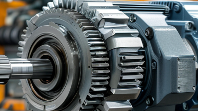
| Gear arrangement | Gears transfer rotational motion through meshing teeth, shafts, bearings, and a lubricated housing. | Single-stage units generally provide lower ratios; multiple stages provide higher ratios. | The selected arrangement determines speed, torque capacity, noise, efficiency, backlash, and mounting options. |
| Helical or spur gearing | Uses cylindrical gears to transmit power between parallel or appropriately arranged shafts. | Typical efficiency is approximately 90%–97%, depending on design and operating conditions. | Provides good efficiency and continuous operation for industrial machinery. |
| Planetary gearing | Uses sun, planet, and ring gears to distribute load across multiple gear meshes. | Typical efficiency is approximately 90%–97%; high torque density is possible. | Well suited to compact, high-load, and precision motion systems. |
| Worm gearing | Uses a worm screw and worm wheel to provide substantial speed reduction, often between non-parallel shafts. | Efficiency commonly ranges from approximately 50%–90%, depending on ratio, geometry, lubrication, and speed. | Offers compact high reduction and may provide limited back-driving resistance, but can generate more heat. |
| Key selection factors | Choose the reducer from required speed, continuous and peak torque, duty cycle, mounting position, backlash, environment, and service life. | Allow for starting torque, shock loads, thermal capacity, lubrication requirements, and output shaft loading. | Correct sizing improves reliability, efficiency, operating safety, and overall system performance. |