Inquiry
Leave Your Message

What Is a Metal Gear Motor and How Does It Work?

A Metal Gear Motor combines an electric motor with a metal gear train in one compact unit. It converts electrical energy into controlled rotational movement. The motor usually spins quickly, but it produces limited torque. The gears reduce speed and increase usable torque at the output shaft. Small motors. Stronger movement.

Inside the housing, electric current creates a magnetic field that turns the motor’s rotor. The rotor drives the first gear, which transfers motion through several smaller gears. Each stage changes speed, torque, and direction. A robot wheel may turn slowly while carrying a heavy load across a rough floor. That practical balance makes this motor useful in automation, mobile devices, conveyors, and precision mechanisms.

However, the explanation should not make the system seem perfect. Gear reduction increases torque, but friction also causes energy loss. Metal gears can withstand demanding loads, yet they may create noise, backlash, and heat. Proper selection requires checking voltage, rated speed, stall torque, duty cycle, shaft load, and mounting conditions. Manufacturer specifications remain essential evidence, especially when performance claims appear attractive. A motor that works well on a test bench may struggle after hours of repeated starts. This guide examines how the motor operates, how gear ratios affect performance, and why real-world conditions can challenge simple calculations. Some assumptions may fail. Careful testing still matters.

What Is a Metal Gear Motor and How Does It Work?

Definition and Core Components of a Metal Gear Motor

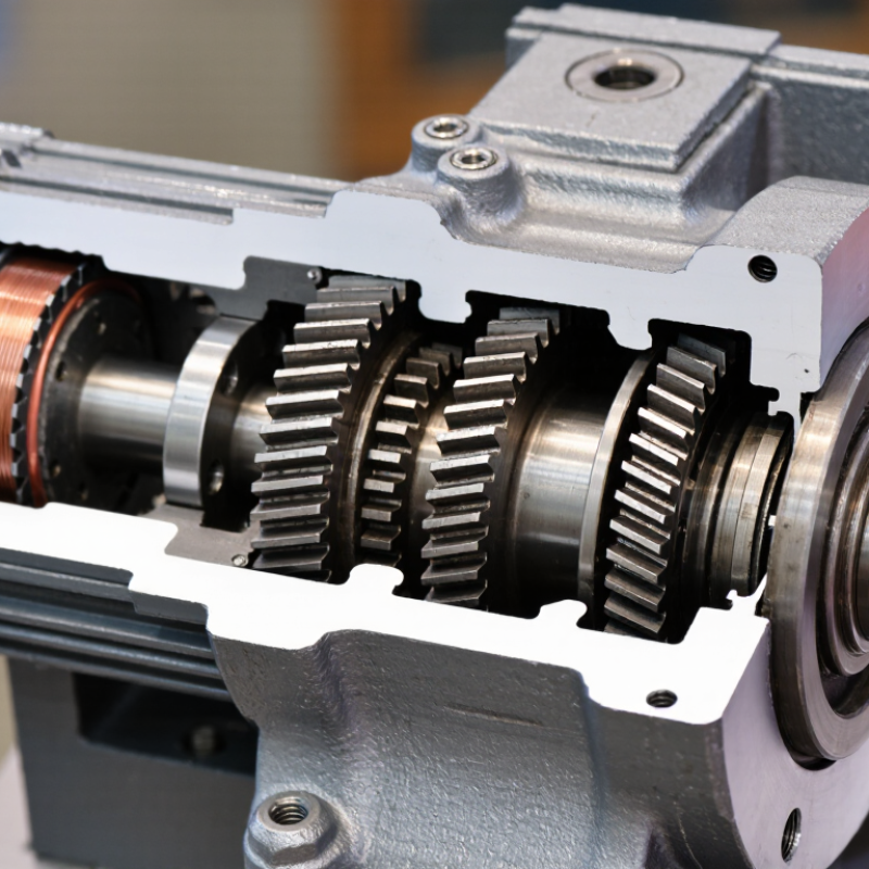
A metal gear motor combines an electric motor with a compact gearbox. The motor creates rotational motion, while the gearbox changes speed and torque. Its metal construction supports steady operation under demanding mechanical loads. Unlike a bare motor, this unit delivers controlled movement through a geared output shaft.

The core components include the motor, gear train, housing, bearings, shafts, lubricant, and output mechanism. The gear train usually contains several metal gears with different sizes. A small input gear turns faster and drives a larger gear. This reduces output speed but increases available torque. Bearings support the shafts and help limit friction. The housing keeps the gears aligned and protects them from dust, impact, and accidental contact.

A metal gear motor works through energy transfer. Electrical power turns the motor’s rotor. The rotor drives the first gear, which transfers motion across the gear stages. The final shaft then delivers usable rotation to a wheel, conveyor, valve, or actuator. In practical testing, noise, heat, and vibration can reveal poor alignment or insufficient lubrication. These signs matter.

One detail is easy to underestimate. Metal does not automatically mean unlimited durability. Excessive load can damage teeth, shafts, or bearings. Engineers should check rated torque, operating speed, duty cycle, voltage, and mounting position before installation. I would also question overly simple specifications. Real performance can change with temperature, lubrication, and repeated starts. A careful selection process often prevents avoidable mechanical failure.

What Is a Metal Gear Motor and How Does It Work?

A metal gear motor combines an electric motor with a metal gear train, shafts, bearings, and a protective housing. The gear train reduces speed and increases torque. The chart shows the theoretical output speed produced by a 3,000 RPM motor at several reduction ratios.

How to read the chart: Output speed is calculated as motor speed divided by gear ratio. For example, a 20:1 reduction changes 3,000 RPM into 150 RPM. Actual output speed and torque can vary because of gear efficiency, friction, load, and motor operating conditions.

How the Motor and Gearbox Work Together

A metal gear motor combines an electric motor with a compact gearbox. The motor creates rotational speed and torque. The gearbox changes that output into more useful mechanical movement. Metal gears are often selected for loads, repeated cycles, and demanding operating conditions.

Inside the motor, electrical energy creates a magnetic field around the rotor. The rotor spins quickly, but its raw speed may be too high for a wheel, valve, or lifting mechanism. The gearbox uses different gear sizes to reduce speed and increase output torque. A small driving gear turns a larger gear, producing slower movement with greater force. This exchange causes some energy loss as heat, noise, and friction.

In practical testing, the output shaft should start smoothly without excessive vibration. Grease helps protect the gear teeth, but it cannot correct poor alignment. A motor may stall when the load exceeds its rated torque. That detail is easy to overlook. Higher reduction is not always better, because it can reduce output speed and increase mechanical stress. Designers should check duty cycle, shaft load, temperature, and startup current before choosing a unit. Measurements from the real mechanism matter more than assumptions from a datasheet. Sometimes, the first selection looks adequate but overheats during repeated operation. That result deserves investigation, not a quick replacement.

Types and Key Specifications of Metal Gear Motors

A metal gear motor combines an electric motor with a reduction gearbox. The motor produces rotation, while gears trade speed for usable torque. In practical terms, a fast shaft can turn a small wheel slowly and steadily. This design suits conveyors, valves, compact robots, and positioning mechanisms. The gearbox is usually steel or another metal alloy, helping it withstand repeated loads. Small details matter.

Spur gear motors use straight teeth and offer a simple, economical drive. They can be efficient, but tooth contact may create noticeable noise.

Planetary gear motors distribute load across several planet gears. They usually provide higher torque density, better stiffness, and lower backlash.

Worm gear motors deliver strong reduction in a compact package. However, friction can reduce efficiency and generate heat. I would not select one by torque alone.

Check rated voltage, no-load speed, rated speed, continuous torque, stall torque, and current draw. Gear ratio predicts output speed, but actual performance changes under load. Also verify gearbox efficiency, duty cycle, shaft diameter, radial load, backlash, and operating temperature. A motor that works for ten seconds may fail during continuous service. Startup current often surprises inexperienced users. It can exceed running current several times. Mounting alignment deserves equal attention, because slight offsets can cause vibration and premature wear. Datasheets are useful, yet measured results should guide final selection.

Step-by-Step Operation of a Metal Gear Motor

A metal gear motor combines an electric motor with a metal gear train. The motor creates rotation, while the gears trade speed for torque. This arrangement suits conveyors, valves, small robots, and positioning equipment.

Step by step, electrical current enters the motor winding. Its magnetic field interacts with permanent magnets, producing rotor movement. The rotor turns a small input pinion at high speed. That pinion drives a larger gear, reducing speed and increasing torque. Several gear stages repeat this action. Finally, the output shaft delivers controlled rotation to the load. Bearings support the shafts, while grease reduces friction between the teeth. The metal housing keeps the gear centers aligned under changing loads.

That detail is easy to miss.

During operation, the motor draws more current when resistance increases. A stalled shaft can create rapid heating and damage insulation. Engineers therefore compare rated torque, startup torque, gearbox ratio, duty cycle, and thermal limits. The International Energy Agency reports that electric motors and motor-driven systems consume about 45% of global electricity, making efficient control important (IEA, Energy Efficiency 2023). A U.S. Department of Energy motor-systems guide also emphasizes correct sizing, because oversized motors may operate inefficiently at light loads. Efficiency is never perfect. Gear friction, backlash, vibration, and heat reduce useful output. In practice, lubrication quality and alignment often matter more than expected. A careful test under the real load is still necessary.

Common Applications and Selection Considerations

A metal gear motor combines an electric motor with a metal gearbox. The motor creates rotation, while the gears reduce speed and increase torque. Metal gears usually handle heat, shock, and repeated loads better than many plastic alternatives. However, they can produce more noise and require better lubrication.

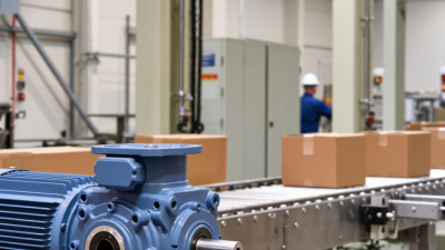
These motors appear in conveyor rollers, automated gates, packaging equipment, medical devices, and small robotic systems. A conveyor may need steady torque at low speed. An automated gate may need short bursts of higher torque. Compact gear motors also drive camera platforms, valve actuators, and positioning mechanisms. The application decides more than the motor’s voltage.

Start with the required output speed and torque. Then check the duty cycle, load direction, starting resistance, and available installation space. A motor rated for continuous operation may fail under frequent starts and stops. Shaft diameter, mounting holes, gear ratio, and gearbox backlash also deserve attention. Backlash can affect positioning accuracy.

Do not select by wattage alone. That shortcut often causes trouble. Allow a practical safety margin, but avoid excessive oversizing. A larger motor may draw more current and respond less efficiently. Dust, moisture, ambient temperature, and cleaning methods can change the correct enclosure rating. In real equipment, alignment is easy to underestimate. Even a suitable gear motor can vibrate when the shaft or coupling is poorly aligned. Specification sheets help, but measured load conditions are more trustworthy.

What Is a Metal Gear Motor and How Does It Work? – Common Applications and Selection Considerations
Data Dimension Typical Information How It Works or Why It Matters Common Applications Selection Considerations
Basic Definition A metal gear motor is an electric motor combined with a mechanical gearbox, usually enclosed in one compact assembly. The motor produces rotational speed, while the gearbox reduces speed and increases output torque. Automated equipment, appliances, robotics, conveyors, and small machinery. Confirm the required output speed, torque, duty cycle, mounting arrangement, and available power supply.
Primary Power Sources Common options include low-voltage direct current and alternating current designs. DC versions are often controlled by changing voltage or using electronic speed control. AC versions are generally selected for fixed-speed industrial operation. Battery-powered devices, control systems, factory equipment, pumps, and ventilation systems. Match the motor voltage, frequency, current capacity, and controller type to the system power source.
Typical Gear Ratio Approximately 3:1 to 1,000:1, depending on the gearbox design and required output speed. A higher ratio normally provides lower output speed and greater torque multiplication, although efficiency and size may be affected. High-ratio designs are used in actuators, positioning mechanisms, lifts, and slow-moving automation. Choose the lowest ratio that meets the torque requirement when efficiency, heat, and response time are important.
Output Speed Often ranges from below 1 revolution per minute to several hundred revolutions per minute in geared systems. Output speed is approximately the motor speed divided by the gear ratio, subject to slip, loading, and gearbox characteristics. Turntables, indexing systems, feeders, window mechanisms, and compact conveyors. Specify continuous speed, minimum and maximum speed, acceleration requirements, and allowable speed variation.
Output Torque Can range from a few millinewton-metres in miniature mechanisms to hundreds of newton-metres in larger assemblies. The gearbox increases torque approximately in proportion to the reduction ratio, minus mechanical losses. Valves, linear actuators, robotic joints, material-handling systems, and lifting mechanisms. Calculate running torque, starting torque, peak torque, and any additional torque caused by friction or acceleration.
Gearbox Types Common metal gearbox configurations include spur, helical, planetary, worm, and bevel gear systems. Each type balances torque capacity, efficiency, noise, size, backlash, and self-locking behavior differently. Spur gears for economical drives; planetary gears for high torque density; worm gears for high reduction ratios; bevel gears for angled power transmission. Select the gear type according to load, efficiency, allowable backlash, orientation, noise limits, and space constraints.
Motor Technology Available motor types include brushed DC, brushless DC, induction, synchronous, and stepper motors. The motor type determines controllability, maintenance needs, starting behavior, noise, and operating efficiency. Brushed DC for simple variable-speed systems; brushless DC for long service life; stepper motors for controlled positioning; AC motors for industrial drives. Consider required positioning accuracy, expected operating hours, maintenance access, controller compatibility, and cost.
Torque-Speed Relationship Output torque and speed are inversely related within the motor and gearbox operating limits. Increasing mechanical load generally reduces motor speed and increases current demand. Operating beyond rated torque can cause overheating or premature wear. Any application requiring controlled motion under changing loads. Use the manufacturer’s torque-speed curve rather than selecting the motor from no-load speed alone.
Efficiency Overall efficiency commonly falls between approximately 40% and 90%, depending on motor type, gear design, ratio, speed, and load. Gear meshes, bearings, seals, electrical resistance, and control electronics all create losses. Battery-powered products, energy-conscious automation, and continuously operating equipment. Evaluate efficiency at the actual operating point, especially for battery systems or applications with continuous duty.
Backlash Backlash is the angular clearance between mating gear teeth. Its value varies widely by gear quality, size, and reduction ratio. Backlash can cause positioning error, lost motion, and mechanical noise when the direction of rotation changes. Robotic joints, camera positioning systems, precision feeders, and indexing mechanisms. Choose low-backlash gearing when repeatability and positional accuracy are more important than minimum cost.
Duty Cycle Typical duty classifications include intermittent, periodic, and continuous operation. Continuous operation generates sustained heat, while frequent starts and stops increase electrical and mechanical stress. Intermittent duty in locks and actuators; continuous duty in conveyors, fans, and dosing systems. Define operating time, rest time, start frequency, load profile, and ambient temperature before sizing the motor.
Starting and Stall Conditions Starting torque is the torque available from rest; stall occurs when the motor cannot rotate under the applied load. A stalled motor may draw high current, producing rapid heat buildup and possible winding or controller damage. Lift mechanisms, jam-prone conveyors, valve drives, and actuator systems. Check starting torque, stall torque, current limits, overload protection, and whether the load can become mechanically locked.
Materials and Construction Metal gearboxes commonly use steel, hardened steel, sintered metal, aluminum, or other engineered alloys for gears and housings. Material choice affects strength, wear resistance, weight, heat dissipation, corrosion resistance, and noise. Steel gearing for high loads; aluminum housings for reduced mass; corrosion-resistant materials for demanding environments. Review load capacity, temperature, humidity, chemical exposure, shock loading, and required service life.
Noise and Vibration Noise depends on gear tooth profile, surface finish, speed, lubrication, alignment, bearings, and housing design. Helical and planetary arrangements can operate more smoothly than basic spur gearing, but design and operating conditions remain important. Office equipment, medical devices, laboratory instruments, household products, and indoor automation. Specify maximum sound level, vibration limits, operating speed, and mounting stiffness if quiet operation is required.
Thermal Management Heat is produced by electrical losses in the motor and frictional losses in the gearbox. Excessive temperature accelerates lubricant degradation, reduces insulation life, and can permanently damage components. Compact enclosures, high-load actuators, continuous conveyors, and high-ambient-temperature equipment. Check rated temperature, ventilation, housing heat dissipation, overload duration, and allowable winding temperature.
Environmental Protection Protection levels may range from open or ventilated construction to sealed enclosures rated against dust and water ingress. Seals and enclosure design help protect the motor and gears from contaminants, but may increase friction and heat retention. Outdoor equipment, food-processing machinery, dusty automation, and washdown-prone systems. Specify the required ingress protection, humidity range, operating temperature, corrosion exposure, and cleaning method.
Control Options Control may be simple on/off switching, pulse-width modulation, closed-loop feedback, or variable-frequency control. Feedback from encoders, Hall sensors, or other sensors can improve speed and position regulation under changing loads. Robotics, automated guided systems, precision actuators, smart appliances, and adjustable-speed conveyors. Determine whether the application needs speed regulation, position feedback, braking, soft start, or synchronized motion.
Common Applications Metal gear motors are widely used where compact size, controlled speed, and increased torque are required. The integrated motor and gearbox simplify mechanical design and reduce the need for separate couplings and supports. Conveyors, vending mechanisms, electric locks, window openers, pumps, medical equipment, robotics, printers, and automated valves. Prioritize torque, speed, size, service life, noise, environmental protection, and control requirements for the specific application.
Service and Maintenance Many small gear motors are sealed for life, while larger units may require inspection, lubrication, or bearing replacement. Proper lubrication and alignment reduce tooth wear, bearing damage, friction, and operating noise. Industrial automation, machinery with scheduled maintenance, and equipment operating under heavy or dusty conditions. Consider access for inspection, lubricant compatibility, replacement parts, expected service hours, and maintenance intervals.
Recommended Selection Sequence Define load and motion requirements first, then select the motor, gearbox, control method, and mechanical interface. A practical sequence is: calculate load torque, determine output speed, check duty cycle, verify thermal limits, and confirm mounting and shaft dimensions. New product design, equipment upgrades, prototype development, and replacement projects. Allow a sensible safety margin without excessive oversizing, which can increase cost, current demand, and physical size.

Note: The numerical ranges shown are general engineering reference values. Actual performance depends on the motor construction, gearbox design, operating point, load profile, temperature, lubrication, and control method.